-
December 15th, 2012, 05:11 PM
#1
Senior Hostboard Member

Altec N-1600-A crossover schematic.
Last edited by cradeldorf; December 16th, 2012 at 01:55 AM.
-
December 15th, 2012, 08:15 PM
#2
Senior Hostboard Member

Re: Altec N-1600-A crossover schematic.
Interesting crossover. 12db/octave slope?
-
December 16th, 2012, 01:01 AM
#3
Senior Hostboard Member
Re: Altec N-1600-A crossover schematic.
I have no idea, It's a series crossover I think. I don't really get how it works. They used the inductor to attenuate the HF. I was thinking of building a pair but I wouldn't be able to do the taps on the inductors. All I would be able to do is build an un-attenable one. I wonder if I could use another small inductor to imitate the original attenuation or if it wouldn't work because it has to be part of the LF inductor?
Last edited by cradeldorf; December 16th, 2012 at 01:07 AM.
-
December 16th, 2012, 01:09 PM
#4
Senior Hostboard Member

Re: Altec N-1600-A crossover schematic.
cradledorf,
Thanks for posting the N-1600-A. It's one of the few Altec duplex crossovers I never had the opportunity to open up and examine. It's a series crossover, as you suspected, using first-order filters and taps on the inductor for HF attenuation steps. You could recreate it with mutiple inductors, or substitute a continously variable resistor shelving control instead like the N-1500-A used later on with the 604E.
Jeff
-
December 16th, 2012, 02:49 PM
#5
Senior Hostboard Member
Re: Altec N-1600-A crossover schematic.
Thanks Jeff, I used the sketch I made as I was dissecting it and the Altec 604E schematic you have on your site to put it all together. Hopefully it helps others because a N-1600-A schematic on the net is pretty much non existent.  Since were on the subject, I understand the variable resistor on the "E" crossover (R2) but what purpose does the other resistor have (R1)? Considering the size I would be tempted to assume it's an attempt at a zobel?
Last edited by cradeldorf; December 16th, 2012 at 03:14 PM.
-
December 16th, 2012, 04:42 PM
#6
Senior Hostboard Member

Re: Altec N-1600-A crossover schematic.

Originally Posted by
cradeldorf

I have no idea, It's a series crossover I think. I don't really get how it works. They used the inductor to attenuate the HF. I was thinking of building a pair but I wouldn't be able to do the taps on the inductors. All I would be able to do is build an un-attenable one. I wonder if I could use another small inductor to imitate the original attenuation or if it wouldn't work because it has to be part of the LF inductor?
- Here's a calculator ( from LHF ) that might help you build your own autotransformer ( though , I've never used it ).
- Ostensibly, your coils should be kept together so that they are working as a single, unified inductor / but the problem with that, is that Mutual Inductance of all the coils together gives a final inductance figure that is larger than the sums ( of the individual coils ) .
- ie; One can't simply add a .75mH coil onto a 2.25mH coil and expect the resulting coils inductance will be 3 mH ( assuming you stack the coils in their proper orientation & that they are wired in series the result will be larger than 3 mH ) .
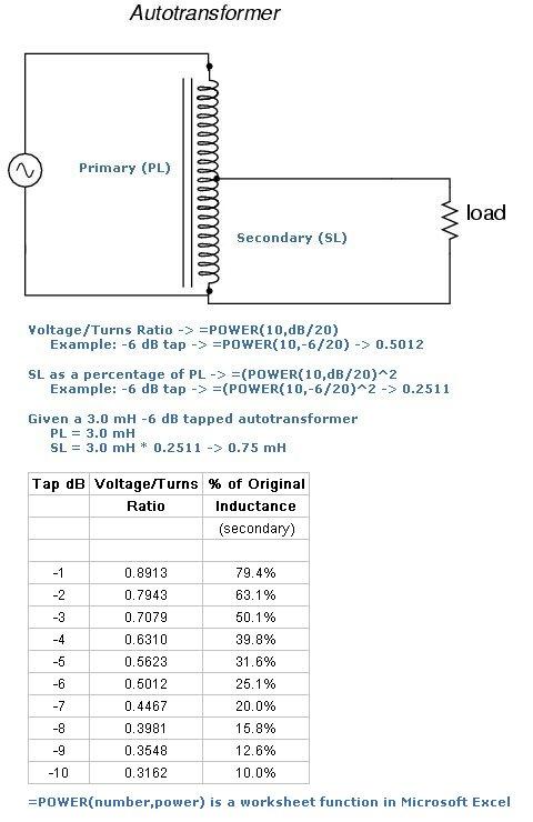
- Running one example ( to find the winding ratio for the -6 db point ) is; power of 10(-6/20) = .5012
- Running another ( to find the winding ratio for the -3 db point ) is; power of 10(-3/20) = .708
-
December 16th, 2012, 08:36 PM
#7
Senior Hostboard Member
Re: Altec N-1600-A crossover schematic.
Originally Posted by
cradeldorf
Thanks Jeff, I used the sketch I made as I was dissecting it and the Altec 604E schematic you have on your site to put it all together. Hopefully it helps others because a N-1600-A schematic on the net is pretty much non existent.
Since were on the subject, I understand the variable resistor on the "E" crossover (R2) but what purpose does the other resistor have (R1)? Considering the size I would be tempted to assume it's an attempt at a zobel?
cradledorf,
You're right about N-1600A references being hard to find on the net.
R1 & R2 on the N-1500A crossover provide a voltage divider to selectively shunt part of the HF energy going to the HF driver. This is a simple type of "tone control" that does not have constant impedance like an L pad attenuator, but is pretty close to the desired impedance when adjusted to the "normal" listening level. When adjusted, it varies from constant impedance a bit more. Simple but effective.
Jeff
 Posting Permissions
- You may not post new threads
- You may not post replies
- You may not post attachments
- You may not edit your posts
-
Forum Rules
This forum has been viewed: 28131802 times.





Bookmarks